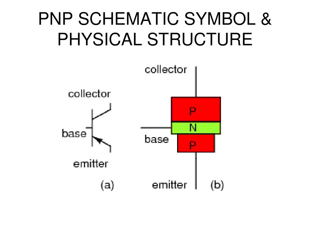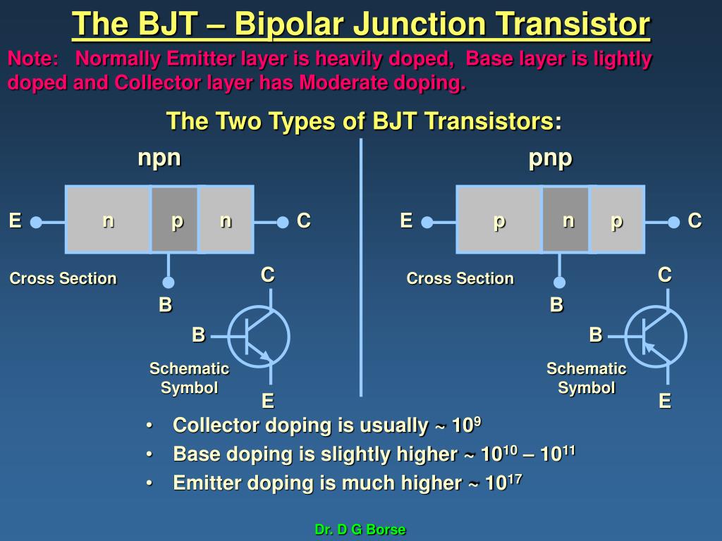
The process of explaining this starts from a 1D to a 2D to the real 3D process but they are real 3D parts shown by symbolic logic diagrams so that you learn to associate the logic with the bipolar or analog characteristics of the basic NPN or PNP BJT. However, in the material that follows, we focus our discussion on what may be the most popular structure and configuration, i.e. Based on operation, MOSFETs are classified into Enhancement MOSFET (p-channel and n.

It has a metal layer at the top, a silicon oxide insulation beneath that and a semiconductor part at the bottom giving it a vertical structure of p and n layers. Not to be confused with the popular N-type MG convertible. Metal Oxide Semiconductor Field Effect Transistor is a voltage controlled unipolar switching device. If two separate pieces of material were used, this would introduce a grain boundary between the semiconductors that would severely inhibit its utility by scattering the electrons and holes.

The p-n junction is created by doping, for example by ion implantation, diffusion of dopants, or by epitaxy (growing a layer of crystal doped with one type of dopant on top of a layer of crystal doped with another type of dopant).

Each layer is made from different materials of either semiconductors between metallic electrodes added to leads, pads or balls then encapsulated.Įach region is doped with fuming hot pressurized chemicals in each layer to make n or p-type materials with various concentrations and depths. The epiwafer is cut and polished from a large cylinder of pure monocrystal silicon.Įach layer like a multilayer printed circuit board is applied with photomasks so that the next process can etch features with a laser, then the mask is dissolve and the next layer is masked, deposited, etched, dissolved, rinsed then then repeated. Many (!) transistors are made in layers by depositing over an insulating substrate of silicon.


 0 kommentar(er)
